Why 50-ohms Mailbag
Regarding my article "Why 50Ω?" (EDN, Sept 14, 2000, pg 30), I received some interesting justifications for the use of 50-Ω coaxial cabling:
In the early days of solid-conductor, high-power, coaxial cables, a common impedance was 51.5V. This impedance was partially due to the use of standard sizes of copper pipe for the inner and outer conductors.— Bob Stroupe
Back in my school days nearly 40 years ago, I was told that a 50-Ω coax delivered the maximum power for given limits on current density on the conductors (or perhaps only the inner conductor) and voltage gradient in the dielectric.—Bruce Carsten
The 50-Ω value is a compromise between high power (30 Ω), high voltage (66 Ω), and minimum insertion loss (75 Ω). —Raymond P Meixner
A half-wave dipole in free space has a feed-point impedance of approximately 73 Ω. A quarter-wave antenna with a ground plane has a feed-point impedance of approximately 37 Ω. A compromise between the two, ratiometrically, is 51.97 Ω, which produces an SWR of 1.404-to-1 either way.—James C Bach
Some readers recognized the minimum-loss-impedance theorem but remembered only the historical value for an air-dielectric cable:
Hate to be the bearer of bad news, but the minimum-loss Z0 for coax is about 70 Ω, not 50. This was first derived during the World War II era.—Jim Rautio
Sorry Jim, it's you who are wrong. Pre-World War II coax transmission lines often used an air dielectric, because the alternative available dielectric materials all had too much dielectric loss. Small insulating "holders" spaced every so often along the line supported the center conductor. The overall structure was rigid and could not be easily bent.
The development of polyethylene changed everything: Polyethylene made possible the production of cheap, flexible coaxial cables, which in turn enabled the deployment of military radar, which helped win World World II.
If you are building an air-dielectric transmission line εR=1.00), then 76.6Ω is the minimum-loss impedance value. That theorem is the one that so many people remember. For cables having a solid-polyethylene dielectric (εR=2.25), 51.1 Ω is the minimum-loss impedance value. You can also get a foamed polyethylene dielectric, or cellular polyethylene, whose properties fall between solid polyethylene and air. Figure 1 plots the relative-loss properties of all three materials.
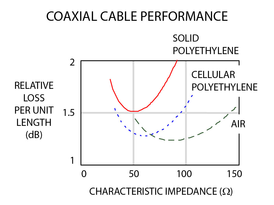
Figure 1—For coaxial cables of a given outer diameter, a dielectric made of solid
polyethylene generates more skin-effect loss than cellular polyethylene or air.
I received several questions about impedances other then 50 and 75 Ω:
Why 93Ω coax?—Craig Miller
IEC Publication 78 (1967) defines standard coaxial-cable impedances of 50, 75, and 100 Ω. The 50 and 75-Ω values remain popular, but the 100-Ω value fell out of fashion. Today, the highest commonly available impedance for coaxial cable is 93 Ω. IEC Publication 78 provides no rationale for the values selected. Standards publications rarely do, because each member of the standards committee usually harbors his or her own reasons for supporting the final solution.
In my experiences, 50 Ω is a good low-loss value for use with cheap, solid-polyethylene dielectrics. It works with most test equipment. Ethernet went with 50- rather than 75-Ω coax, because a 50-Ω cable is more tolerant of the capacitive loading effects of the transceiver taps.
If you can afford a rigid-air dielectric cable, 75 Ω works best. The 75-Ω impedance also closely matches the input impedance of a half-wave dipole antenna, which accounts for its popularity with RF engineers. Why do video folks use 75-Ω cables? I can only assume that they inherited this preference from their radio-engineering roots.
The most plausible explanation I have heard for 93 Ω is this, "Wimpy drivers appreciate higher impedance transmission lines."
Why 150-Ω shielded twisted pair? —Silence Dogood
I consider IBM's selection of 150-Ω impedance for their flagship Type-I data cabling in the early 80's to have been a monumental goof. IBM would have achieved less skin-effect loss using a 100-Ω differential impedance within the same jacket. When this cable was developed, IBM's engineers touted 75-Ω coax as optimal. So, they reasoned, when you put two center conductors in the same jacket, the best differential impedance has to be 150 Ω. Unfortunately, the math supports that conclusion only for an air dielectric. With the dielectric IBM chose, a 100-Ω differential impedance would have been a better choice. Or, for the same loss, they could have designed a smaller, more easily handled cable.