Scattering Parameters
Have you ever finished a big project--and then the next morning wished you could have added just one more feature? Well, thanks to the miracle of the internet, I get to keep writing all the articles I want to supplement the information in my latest book, High-Speed Signal Propagation. This article on Scattering Parameters (S-parameters) relates the transmission matrices described in that book to the S-parameter matrices provided by a network analyzer.
Scattering Parameters
by Dr. Howard Johnson
A scattering matrix (S-parameter matrix) is one way to describe the operation of a linear, time-invariant two-port circuit. A two-port network is defined as any linear device where a signal goes in one side and comes out the other.
The S-parameter matrix is rapidly becoming very popular as a way to characterize connectors and cables for high-speed applications above 1 Gb/s.
The measurement setup associated with S-parameters is as follows (Figure 1).

From the test equipment, two cables having characteristic impedance Z0 lead to the left and right sides, respectively, of the device under test (DUT).
Using the first (left-side) cable, inject a sinusoidal signal (in1) of unit amplitude into the DUT. The test equipment records the amplitude and phase of the signal (out1) reflected back onto the first cable from the DUT, and also the amplitude and phase of the signal (out2) conveyed through the DUT to the second cable on the other side.
In a separate experiement, using the second (right-side) cable, inject a sinusoidal signal (in2) of unit amplitude into the DUT. The test equipment records the amplitude and phase of the signal (out2) reflected from the right side of the DUT, and the amplitude and phase of the signal (out1) conveyed through the DUT to the other (left) side. The complete S-parameter matrix is a combination of these four basic measurements.
The four elements of an S-parameter matrix may be reported as complex numbers (with real and imaginary parts) or in logarithmic units (as dB magnitude and phase).
NOTE: This procedure as I described it measures circuit performance at only one single frequency. The entire procedure is usually performed on a dense grid of frequencies spanning the range of interest, such that the parameters s11, etc., are all functions of frequency.
Provided that the reflection coefficients s11 and s22 are relatively small, you may estimate the effect of cascading several two-port networks by merely multiplying the s21 coefficients of the individual components (or, if they are in logarithmic units, by adding the dB values of the s21 coefficients). Such a calculation determines, TO FIRST ORDER, the magnitude and phase of a signal that propagates straight through the cascade proceeding from left to right through each component. This is the beauty of S-parameter analysis, and one key reason it is used in the design of highly cascaded systems like radio receivers and chains of linear amplifiers.
Unfortunately, the overall transfer function of a highly cascaded system equals the product of the s21 terms if and only if the reflections are all negligible. If the reflections are significant, the gain does not equal the product of s21 terms.
If you want to model a system with reflections, a more sophisticated analysis is required. That's the purpose of the Transmission Matrix, also called the Transfer Matrix, or A-parameters.
The measurement setup associated with transmission parameters is defined as follows (Figure 2).

The four transmission parameters are measured by first stimulating the circuit on the left side (V1 and I1) while holding the right side open-circuited. This condition ensures I2=0, under which condition you may easily determine a11 = V1/V2 and a21 = I1/V2.
Then the right side is shorted to ground, ensuring V2=0, while you measure a12 = V1/I2 and a22 = I1/I2.
The measurements are repeated on a dense grid of frequencies spanning the range of interest, such that the parameters a11, etc., all become functions of frequency.
One difficulty associated with transmission parameters is that in a practical high-frequency circuit it is extremely difficult to obtain the perfect open-circuit and short-circuit conditions required to make good measurements. For example, the open-circuit measurement is always corrupted by parasitic capacitance shunting port 2. The short-circuit measurement is corrupted by parasitic inductance in series with port 2.
The S-parameter method circumvents the open/short difficulties by always connecting both ports to transmission lines with stable, well-defined impedances. To the extent that such a test setup better represents the actual working conditions of your circuit, the S-parameter method generates a more accurate model. Note, however, that the S-parameter method requires that the measurements be made at some particular impedance Z0. For best results, this impedance should be reasonably close to the impedance under which your circuit element will actually operate.
To make clear the importance of the test-circuit impedance, consider that a good 50-ohm connector, if implemented with proper vias, and when measured with Z0=50 ohms may exhibit very small reflection coefficients s11 and s22. The same connector, if measured with a test impedance of Z0=75 ohms might produce terrible reflection coefficients. The values of the S-parameter matrix are thus quite sensitive to the impedances used during the test. The subject of correcting an S-parameter matrix to compute the result you would have gotten at a different level of test impedance is considered at the end of this article.
The transmission parameters are the parameters best suited for calculating the performance of cascaded systems, taking into account reflections.
Given a set of system components represented by transmission matrices A, B,...Z, the transmission matrix representing the cascaded combination of all three pieces is constructed by simply forming the matrix-multiplication product of all the pieces: AB...Z. The resulting combined transmission matrix properly represents all the transmission gains and all the internal reflections associated with the combination of system components.
The transmission-matrix description excels at modeling systems that incorporate multiple cascaded sections with noticeable reflections, such as a chip I/O driver followed by a chip package, a pcb trace, a connector, another pcb trace, another chip package, and a parasitic load at the receiver.
Supposing that you have an S-parameter description of a connector, and an S-parameter description of a backplane, how do you combine these pieces to produce an S-parameter description of the whole system?
This is done by first converting each S-parameter description to a transmission-matrix description and then multiplying together the transmission matrices corresponding to the system components you intend to cascade. The result is a transmission-matrix description of the whole system.
To facilitate your work, here are the conversions from S-matrix format to transmission-matrix (A-matrix) format. These formulas assume that Z0 is purely real and the same on both sides of the S-parameter test setup. If that isn't true, more complicated formulas apply (see for example, Chan Chan and Chan, "Analysis of Linear Networks and Systems", Addison Wesley, 1972, Lib. Congress Cat. Card No. 70-156589).

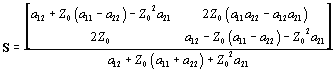
NOTE: The conversion calculations must be repeated done for each frequency on your dense grid. That makes a lot of computation, but why else do we have computers?
Given the source and load impedances in the network you may extract the transmission gain of the system (including the effects of internal reflections) directly from the combined transmission matrix (see Appendix C of High-Speed Signal Propagation).
Alternately, if you have access to an S-parameter simulator you can convert the combined transmission matrix back to a single S-parameter matrix representing the whole system, and then use it. You'll get the same answer either way.
Now let's look at one of the very interesting uses of the transmission matrix: scaling the length of a transmission line.
Sometimes it happens that you have measured the S-parameters of a piece of cable, or a backplane trace, and wish to have an S-parameter description of a longer (or shorter) length of the same cable. The solution to this problem is to first convert the S-parameter description to a transmission matrix, then scale the length, and finally convert back to S-parameters.
To see how length-scaling works with transmission parameters, first consider the simple case of doubling the length of the transmission medium. This effectively cascades two identical sections of transmission line. If the transmission-matrix for a single section of line is A, then the result for a double-length section would equal A2 (using matrix multiplication). Further integer-length extensions are provided by compounding higher and higher powers of the matrix A, such that the complete model for a section n-times longer than the basic unit section equals An.
An even more interesting fact (which I don't have space to prove here) is that the power-of-A formula works even for non-integer n, and also for fractional n. Therefore if you want to model a section of transmission line whole length is, say, .316 times the length of your basic unit section you simply form the matrix A0.316.
If you haven't previously encountered the idea of raising a matrix to a fractional power, let me tell you a little about it. The concept is that you first decompose the matrix using an eigenvalue decomposition. Routines for eigenvalue decomposition exist in all the major mathematical-spreadsheet packages (MatLab, Mathematica, and my favorite, MathCad). The eigenvalue decomposition produces three matrices, U, D, and V, which when multiplied together (UDV) equal your original matrix A. Without going into a lot of detail, the matrix D is always a diagonal matrix. The diagonal elements of D are called the eigenvalues of A (see any book on linear algebra, for example Gilbert Strang, "Linear Algebra and Its Applications", Academic Press, 1976, ISBN 0-12-673650-2). To form the matrix Ax for any value of x, form a new matrix E by raising each element of the diagonal matrix D to the power of x, and then use your new E to form a new matrix UEV, which becomes your answer. Convert UEV from transmission-matrix format back to S-parameter format and you now have a length-scaled S-parameter model of the whole system.
Let me advise you that such manipulations work best on systems, such as long uniform transmission lines, that incorporate few if any internal reflections. It's OK if you have reflections at the front and back ends of the line, as those will properly scale in time, but if you have internal reflections (such as vias) internal to your unit-length standard measurement then when you scale that measurement to, say, half length the equations will produce some kind of system with different internal reflections, such that when you cascade two half-length systems in series you will get the original reflection pattern observed during the test. That answer is mathematically correct, but it probably isn't what you want. The original unit-length S-parameter setup should incorporate only the main body of the transmission structure, not any imperfections along the way. Any mismatches at the ends of the transmission structure are properly handled by this technique.
My final subject has to do with correcting the value of Z0 used during S-parameter characterization.
The conversion from S-parameter to transmission-matrix format depends in each direction upon an assumed value for the characteristic impedance Z0 of the test setup. If you have made S-parameter measurements at one level of impedance and wish to see what S-parameter matrix you would have gotten with a different level of impedance Z1, then convert from S-parameters to transmission-parameters using Z0, and then go back the other way using Z1.
I hope these brief comments are helpful to you.
Best Regards,
Dr. Howard Johnson